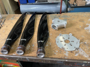

- Assemble the propeller on a table.

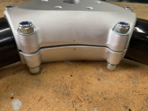
2. Make sure “0” marks on the propeller hub halves are aligned. Do not tighten the blade fixation bolts.

3. Install the propeller with the spinner base plate on the engine flange.

4. Tighten the propeller attachment bolts with 1.5 N·m torque to ensure friction between the blades and the hub halves necessary to set the blades angle. Leave the blade fixation bolts untightened.


5. Tighten the screw of the movable plate of the propeller pitch gauge to reliably fix it with friction in the required position. Set the movable plate to the required propeller pitch. The recommended pitch for A22/A22L/A22L2/A22LS is 1.5 and for A32/A32L is 1.6.


6. By lightly hitting the surface of the blade near its trailing edge, set the required pitch. When checking the pitch, the gauge should be based on the front face of the hub while the movable plate of the gauge should touch the surface of the blade without effort. The gaps at the points of contact of the gauge and the blade surface are not allowed.


7. Tighten the fixation bolts of the blade adjusted to the required pitch with 10 N·m torque.

8. Repeat steps 6 and 7 for the remaining blades. The propeller may be rotated for convenience. Check the angle of installation of all the blades using the propeller pitch gauge.
9. Tighten the propeller attachment bolts with 25 N·m torque.


10. Check the angle of installation of all the blades using the propeller pitch gauge.
11. Tighten the blade fixation bolts with 25 N·m torque.


12. Check the angle of installation of all the blades using the propeller pitch gauge.
